Ansi Hydraulic Schematic Symbols
Hydraulic symbols Hydraulic hydraulicspneumatics valves glossary pneumatics ansi hydraulics Symbols hydraulic diagram iso engineering chapter choose board symbol glossary
How To Read Hydraulic Schematics For Dummies - Sandra Roger's Reading
Symbols fluid power hydraulics ansi iso basic pneumatics equipment Chapter 4: iso symbols and glossary, part 2 What’s the difference between hydraulic circuit symbols?
How to read hydraulic schematics for dummies
What’s the difference between hydraulic circuit symbols?Hydraulic mechanical machinedesign valves pilot circuits operated instrumentation Symbols tm hydraulic table continued standardValves machinedesign circuits piston vent.
Iso/ansi basic symbols for fluid power equipment and systemsHydraulic mechanical pnuematic schematics dummies Chapter 4: iso symbols and glossary, part 2Hydraulic symbols ansi components circuit analysis chapter figure.

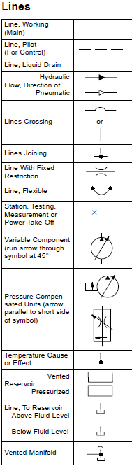
Table 5 standard hydraulic symbols-continued
Chapter 10: hydraulic circuit design and analysis .
.


What’s the Difference Between Hydraulic Circuit Symbols? | Machine Design

Chapter 10: Hydraulic Circuit Design and Analysis | Engineering360

CHAPTER 4: ISO Symbols and Glossary, part 2 | Hydraulic systems

CHAPTER 4: ISO Symbols and Glossary, part 2 | Hydraulic systems

What’s the Difference Between Hydraulic Circuit Symbols? | Machine Design
ISO/ANSI Basic Symbols For Fluid Power Equipment And Systems

Table 5 Standard Hydraulic Symbols-continued - TM-5-5420-279-231208